While browsing Buyee before bed as everyone does (right?), I spotted a good deal on a Sharp MD-ST70
that was in pretty good condition. This is a fun little player that has a front LED panel that lights up while doing various functions.

The auction listing said it was working OK, but the remote was flaky. I had a few remotes, so I figured it was worth a gamble for the price. I didn't have one of these units yet, and I liked how the front panel lights up (I'm a simple man...).
Looking good...
Well, I was pleased to see it was indeed in good shape when I received it and popped in a gumstick battery (clean terminals!) and a disc to test it out.
It powered up and I got to witness some flashing lights - nice! The girls will love this!
Sounds pretty good *nodding head to the music*, let's skip a few tracks... GRINDDDDDDD
Yep, it was the dreaded Sharp gear grinding noise that should probably be a meme at this point. For those unaware, it seems that the plastic end of the "worm gear" on Sharp player/recorders is prone to failure (c'mon, it's been 20+ years for some of these models!) and will render them non-functional for most people.
If you're reading this, you (and I) are not "most people".
I've heard and seen articles and videos about changing the gears and they can be pretty intimidating. You're diving deep inside a delicate electronic device that has delicate ribbon cables, components that can be fried by static electricity, tiny screws to lose, and other myriad dangers.
Having honed my skills on some other easier tasks (opening and cleaning/lubing some players, fixing MiniDisc decks with plenty of space to work inside) as well as being a somewhat "handy" DIYer and PC-builder, I decided it was time to replace my first Sharp gear.
Getting a replacement Sharp gear
There are now options on eBay and Hong Kong (via MD Gadgetry on Instagram) but in my case, I found another Sharp player on Buyee for 500 yen (less than $4 USD at current rates) that I hoped could yield a good gear and more misc. parts.
You can always reference a service manual, but I did not (besides, it seems there isn't one readily available on Google for this specific model). I just decided to hop in because these larger Sharp players (in my experience) are fairly easy to open and get into without any shenanigans.
Getting started!
Start by opening the battery compartment lid and carefully sliding it off by pulling it away from the body. If you're careful, it will just take a firm pull without breaking a plastic tab/retainer. Push the metal contacts that were inside the battery compartment a bit inside the body since we'll have to remove the outer shell and we don't want it to snag on that.
As expected, there's a top/bottom half and there are 7 small screws around the perimeter of the bottom half. Note that one of the screws (the one near the bottom where the AA sidecar attaches) is smaller than the others.
From the side of the player where the black headphone jack is, gently pry and try to remove the rear casing. It should lift up from there. Be very gentle since this is nearly 20 year old plastic that has aged. Once that's off, you'll see the following:
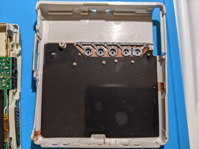
That plastic strip of buttons can fall off easily, but don't worry about that until it's time to reassemble.
This next picture shows both halves and a small metal tab.
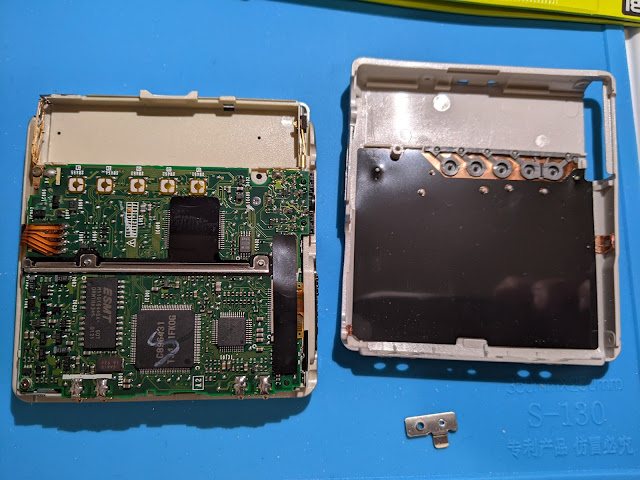
That little metal thing will surprise you when it falls out, but it's simply a reinforcing piece for where the AA sidecar will screw in. As you reassemble later, you will want to place it back into its slot and carefully put the halves back together. It will be tricky, but I'll cover how I did that later (only to make it less tricky, not easy).
We can put the back cover and metal tab aside for now - what we'll want is all contained in the other half with the electronic bits.
As always use proper ESD/grounding procedures when working with delicate electronics!
Let's next show you some "points of interest" on the board below.
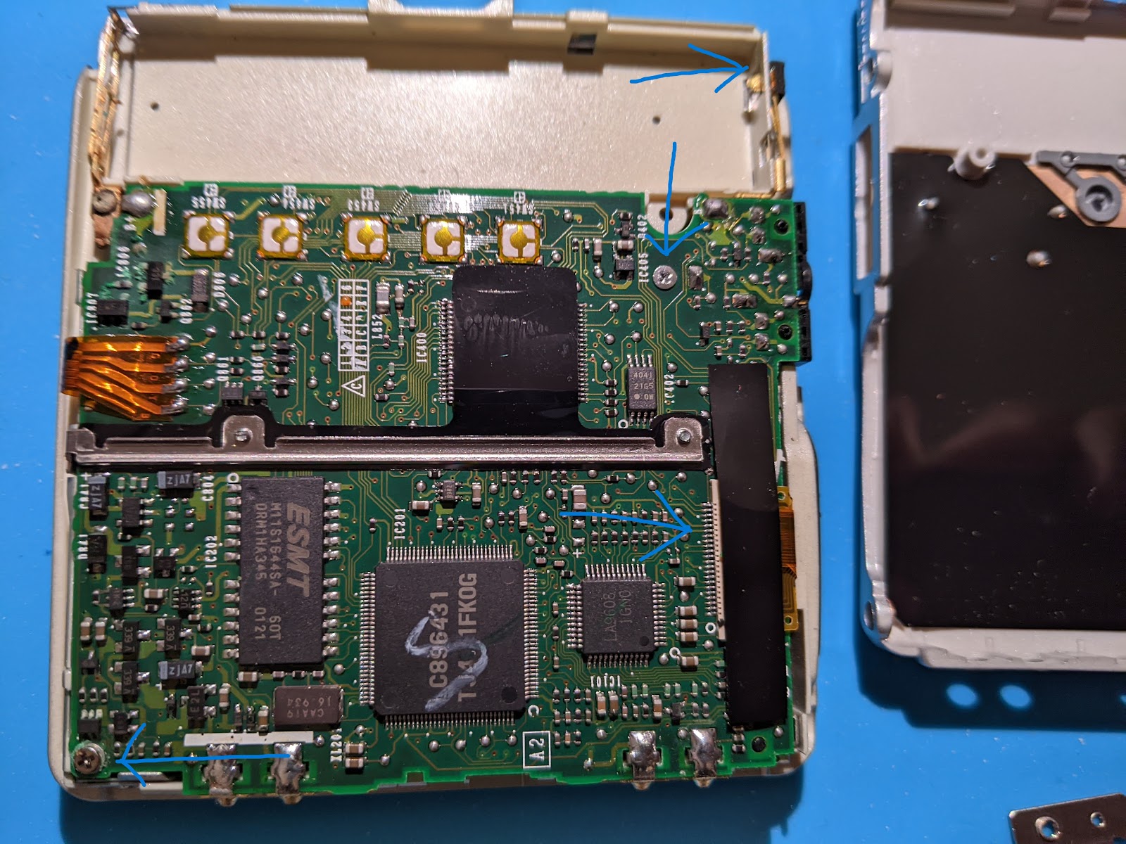
On the right side, you'll see a big rectangular piece of black tape. Under it is a delicate ribbon connector which you'll need to remove before you can get much further.
To do this, carefully lift up the left/right edges of the tape (leaving the center portion still attached to the connector) so you can see underneath. You'll see a plastic retainer where the flat ribbon cable is being held. As usual with these types of connectors, use a small tweezer (or other implement) to pull out the black tabs on the left and right side of the connector. Once they're pulled away from the retainer, you can slide the flexible ribbon cable out with no effort. Please be careful handling that as the exposed end (which was hiding inside that retainer) is very sensitive to static electricity which could lead to ruining the components it connects to.
In the photo above, you'll see two blue arrows for two screws that must be removed and an arrow pointing to where the negative terminal must be pushed back to lift out the board (after removing the aforementioned screws).
Remove the screws and keep track of them. One is short, one is long.
Now it's REALLY quite tricky to do so but not impossible. I think it's easiest to wedge something small under the board so it's propped up at a 30 degree angle and then use your tweezers to get the cable clips then cable out. You can do the same in reverse later.
Otherwise you'd have to desolder the cable on top of the board (which connects to the front lights) and I didn't want to do that.
Now, you should see the laser sled, some gears and the spindle motor in all their glory! Where's that worm gear we're replacing? Oh, it's under a bunch of other stuff...
Going deeper...
To be honest, I removed a lot of stuff that wasn't 100% necessary to replace the gear, but I will say it did make it easier to access everything and lube/clean parts, so you might want to do it anyway.
Additionally, I honestly didn't plan on succeeding here so I didn't document the process as well as I should have... I will try to simulate the photos as well as I can since I still have the donor.
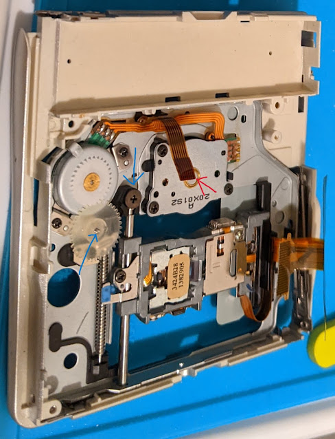
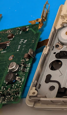
Here, using the donor, you see some gears (blue arrow, left side), a large black screw (blue arrow, top; for that metal shaft that allows the laser sled to move smoothly) and a red arrow pointing to yet another flexible ribbon cable. That cable is attached to the underside of the board (the tricky one mentioned earlier) and must be removed carefully in the same manner as before (slide clips back, pull cable out).

Again, sorry for not taking pics - I wasn't convinced this would actually work...
Looking at the gear itself

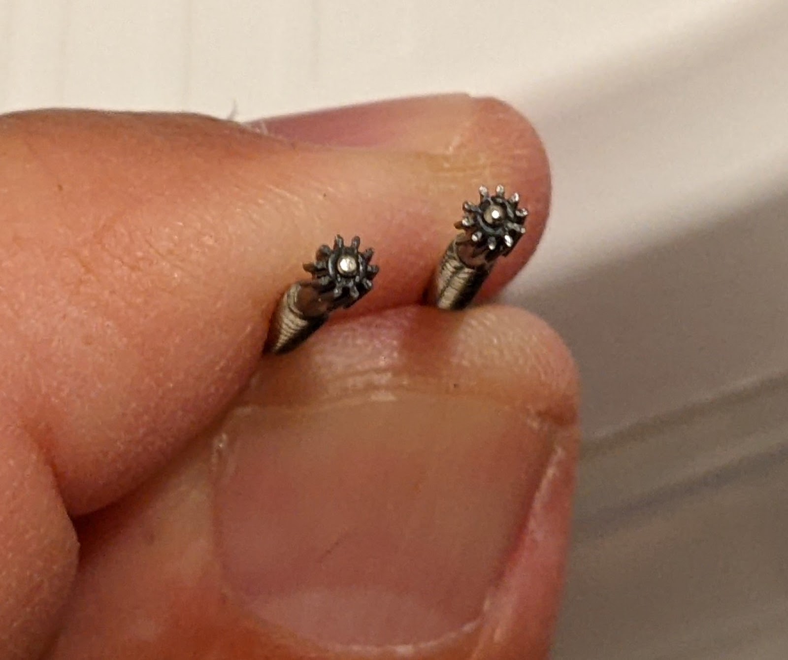
On the left photo, now that you're at an angle, you can see the right-most gear is split/cracked at the top section. Even though it doesn't look like much, these are very precise mechanical devices and that small crack probably means the gear is "spinning" on the rod instead of moving the laser assembly where it needs to be.
Re-assembly
Let's just list this out for brevity:
1 - replace the cracked worm gear/rod with a new/working one
2 - put the metal place over the gear portion and secure it with a screw
2a - if you removed the bottom laser sled rod, replace that and screw in the larger black screw that was holding it
3 - put the translucent gear back over the top of the worm gear's metal plate
4 - push the c-clip or collar back down over the translucent gear
5 - lay the main board you removed on top of the body. Find something to wedge underneath as you connect the smaller ribbon cable to the underside of the board. Curse, stomp, or walk away if you get frustrated and come back. If you have some "helping hands" use them.
6 - once that small ribbon cable is connected, lay the board down and slide in the larger ribbon cable (the one we had to remove the large black tape to access).
7 - press the board carefully into place and watch out for the negative battery terminal fit/placement.
8 - screw down the board
9 - place the metal reinforcement piece (for the external battery pack) into its slot and gently place the back panel on top while trying to keep the metal piece in place.
10 - start screwing things back in, making note of that reinforcing metal piece. It can move around a bit.
11 - snap the battery door's plastic cover back on
12 - cross fingers
It's alive!!!
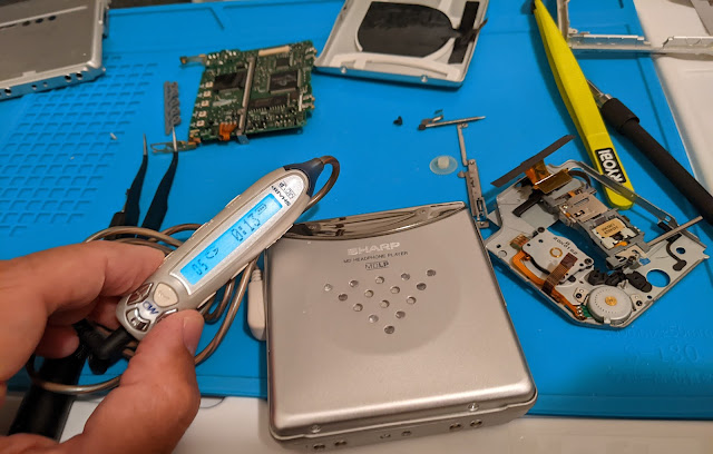
Now that it's back together, slot in a gumstick battery and a disc and let's test it out! If all went well (and the gear was the only issue), then now you have a working Sharp MD-ST70!
I really intended to fix this up and sell it (I have plenty of players), but after "investing" (some say wasting...) a few hours doing this, I decided to keep it. Since then, I've tested it out on a 5+ hour flight and performed perfectly.
I also now have another set of spare screws and parts if/when I have another failure.
I hope that was helpful to someone! Since I am enamored with Sharp players (specifically the Auvi, 1-bit ones), I will get more info out about repairing/maintaining those as well.